|
|
Synths |
| Last Updated: | |
| Syntecno TeeBee T303 (Mark I) | |
| MODS | |
| | Accent Pot | More Volume / VCA | Accent "Wow" | Infinite Decay | IEC Mains / Internal PSU | | |
|
|
Synths |
| Last Updated: | |
| Syntecno TeeBee T303 (Mark I) | |
| MODS | |
| | Accent Pot | More Volume / VCA | Accent "Wow" | Infinite Decay | IEC Mains / Internal PSU | | |
Syntecno TeeBee Mark I T303
Modifications
Except for the IEC Mains
Socket & Internal Transformer / PSU,
the other sound mods are from the download docs from
Syntecno's Homepage.
| Mod1: ACCENT POT | |
| The idea of the Accent Pot: Since the TeeBee is Velocity Sensitive but the original TB-303 is not...
When the TB303
plays a note with an accent, the following 3 things happen : With the TeeBee,
In
order to get “the most TB303-a-like accents” : |
|
| The MOD: Replace R46 with a 50k Lin Pot
Locate R46 on the analogue (front) PCB, |
 [Click Image to Enlarge] |
|
Mounting: |
|
| On my TeeBee Mark I, I put
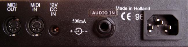
took out the front Audio Input socket and mounted that at the back. So I have a hole there to mount the Accent Pot. |
|
|
New Accent knob replacing the Audio input
Socket: |
|
![]()
| Mod2: More VOLUME (VCA Update) | |
|
The idea of the More Volume / VCA update MOD: For
making the sound larger in volume, resulting in a better signal to noise
ratio. This
modification makes the signal coming from the VCO larger. |
|
| The
MOD: Replace R62 (220K) with a 100k resistor. Or solder another 220K in parallel to the original R62. |
|
| What I did...
Instead of making this a permanent mod, I soldered a SWITCH, so I can switch between the original and the mod. |
|
|
|
|
|
A switch mounted next to the Tuning knob:
|
|
| Note: To be honest, I don't think a switch is really necessary. I only did it so I can compare the difference. But in real life usage, the mod just makes it slightly louder, it isn't a very dramatic effect. |
|
![]()
| Mod3: Accent "Wow" | |
|
The idea
of the Accent "Wow" Mod: |
|
| The
MOD: Replace R138 (27K) with a 68K resistor |
|
|
|
|
| What I did...
Again, I added a switch, to switch between the original and the more "Wow" mod. |
|
|
A switch mounted next to the Filter knob: |
|
![]()
| Mod4: Infinite Decay | |
|
The idea
of the Infinite Decay Mod: Normally, when you put the filter
decay at it's maximum (totally turned right), the filter of the TeeBee
makes the sound to disappear. After approximately 1 minute, the sound has
been filtered so much that the sound of the TeeBee fades away. |
|
| The
MOD: Place a resistor of 10R (10 Ohm) between the right side of R148 and the right side of R143. You can place a switch in series with this resistor in order to be able to switch the decay to infinite or to have normal operation. |
|
|
|
|
| What I did...
Again, I added a switch, to switch between the original and the infinite decay mod. |
|
|
A switch mounted next to the Decay knob: |
|
![]()
| Mod5: IEC Mains Socket + Internal Power Supply | |
|
The idea
of the IEC Mains Socket & Internal PSU Mod: The TeeBee requires an external 12V DC 500mA power adaptor (wall-wart). An IEC socket inlet can be mounted at the near end at the rear panel. |
|
|
|
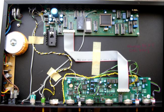
The internal has enough space to house a transformer and a small PSU +12V stripboard, so I think it should be a good idea to mount these inside and add an IEC mains socket. |
|
The wiring of the Power Switch on the
front panel needs to be changed. |
|
|
|
|
| Mains goes to the Power Switch, then to the transformer. | |
| The transformer I used was a Toridal transformer, (RS Part #223-7771). Rated 15VA, this transformer has 2 0-12V secondary - I actually joint them to before I feed to my PSU circuit, so I have 24V-0V-24V into my PSU board. | |
|
The output DC +12V should have enough power >1A, which can power the TeeBee, plus, i can use the original DC in socket at the back and connect to other equipments that needs 12V DC (eg one of my Midi Thru boxes). |
|
| The PSU circuit board is
basically a diode bridge and then an LM-317 rectifier circuit. It is the same as most of the +9V PSU boards I did on my other synths.
Only difference is for +12V, the resistors for the LM-317
are now 470R and 4K. |
|
|
|
|
 |
|
|
|
I don't do custom PCBs, instead I do most
of my stuff on stripboards. The stripboard in this case is 20x10, done on a 30x10 Maplins stripboard, it has quite a lot of space on each end for mounting. The board is then mounted to the very left side of the 19'' rack, next to the toridal transformer. |
|
|
|
| 12V DC output is soldered to the analog PCB, tapped to the underside of the original 12V DC In socket. This way, the original DC In socket can also be used as an output. | |
|
|
|
|
Note: To make the IEC Mains Inlet hole, I use a screwing hand tool, which is an M10 Radius Hand Hole Cutter, 28x21mm (RS Cat.#543-614 or or 541-501), with matching 10A Snap In PCB Mount IEC 320 Plug Socket ( |
|
|
|
|
![]()
![]()
![]()
![]()
![]()